From Field Mapping To Published Map
By Kent D. Brown
Most of us are familiar with photographs of early explorers of the American West, fighting for their lives trying to maneuver overloaded wooden boats down the raging Colorado River. Some of these explorers were geologists determined to map the rugged expanse of unknown territory. Not only did they map the geology, but they also spent long periods of time making relatively crude topographic maps on which the geologic maps were constructed. Today, geologic mapping in Utah continues with the same spirit of exploration and discovery, but of course is being done using vastly superior tools and techniques.
Geologic mapping techniques have undergone major changes since those early days of lugging unwieldy equipment to remote locations in boats and on the backs of men and beasts. As with most technological advances, over the next half century equipment got better, smaller, and less expensive. A major advance came in the 1940s when aerial-photography technology greatly expanded and aerial photos became available to geologists. Drawing geologic features on stereo aerial photos (paired photos that produce a three-dimensional [3-D] image) became commonplace after World War II, and complex machines used to transfer this information onto an accurately scaled map were available; this stereo process is known as photogrammetry. Today this technology continues to advance with digital aerial cameras and photogrammetry accomplished using computer software.
The Geologic Mapping Program of the Utah Geological Survey uses a combination of up-to-date software technologies and proven traditional methods to prepare geologic maps for publication. Field mapping techniques used by geologists are numerous, but producing a preliminary geologic map suitable for open-file release generally involves one of three methods: (1) direct mapping on aerial photographs and then redrawing the geologic features on paper topographic maps (base maps with or without superimposed photographic images), (2) direct mapping on aerial photographs and then using photogrammetry software to digitally transfer the geologic features, in stereo, to a Computer Aided Design (CAD) file compatible with Geographic Information System (GIS) software, or (3) digitally collecting and attributing geologic data in the field using a rugged tablet computer with integrated Global Positioning System (GPS) receiver and geospatial software, which creates GIS data. The term “geospatial” is used here to describe geographic data that are accurately referenced to a precise location on Earth’s surface. Each of these methods has its strengths and weaknesses, and the need for flexibility and individual mapping style make them all valid techniques.
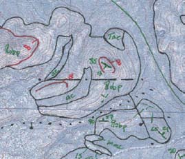
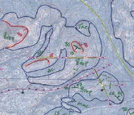
In the first method, we scan and geospatially correct the paper map drafted by the field geologist. Scanning the paper map converts it to a raster image much like a digital camera converts a scene to a file of image pixels. For our maps, this image is then corrected to make it fit a real-world coordinate system. From this geospatially corrected image, the geologic map is digitally vectorized. We use software that converts the raster image to vectors—in other words, it makes lines from image pixels. The result is a multi-layered CAD file that can be imported into GIS software to create a fully attributed geodatabase (computer database of geographic map features) of the geologic map.
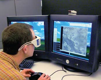
The second method is the most precise and technically advanced way we create geologic maps and reduces errors caused by copying lines twice in the paper map method. Two aerial photographs having 60 percent overlap are referred to as a stereo pair; this overlap is needed to use photogrammetry. When positioned correctly this pair of photos can be viewed in stereo showing 3-D depth of view. However, this stereo view is considered raw or distorted. To accurately map using this photo pair, we scan them at high resolution (1000+ dpi) and save the images as Tagged Image Format (TIF) files. Then, we use photogrammetry software to perform spatial orientations on the TIF images to correct all distortion, accurately scale them, and assign real-world coordinates to this stereo image. When completed, these steps allow the geologist to view the map area on the computer monitor, in stereo, through special glasses. The geologic features are then drawn on the 3-D surface the geologist sees using a software input device known as a “3-D Mouse.” With this process we create a very precise and feature-rich 3-D CAD file that is then imported into GIS software to create a geodatabase of the geologic map.
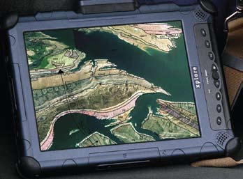
The third method allows the mapping geologist to use a rugged tablet computer and GIS software in the field (see companion article in this issue). Digital base map images are displayed on the screen for positional reference; among them are topographic, geospatially corrected photographic (orthophoto), and shaded-relief maps, as well as images of other geologic maps. The GIS software is configured to use data input forms, with pull-down pick-lists, to simplify and standardize the collection of geologic data. It can also store field notes and digital photographs of sights in the field mapping area. This method allows the geologist to create a digital map in the field with attributed and colored map-unit polygons, geologic symbols, and feature labels. Although the tablet computer cannot display stereo images, and geologic lines drawn using the tablet tend to be less precise than when using photogrammetry, use of the tablet can save significant amounts of time in the overall mapping process.
Regardless of which method is employed, the preliminary data are used to make inkjet plots of the maps for review. After the geologist’s review, GIS analysts in the UGS Geologic Mapping Program create GIS geodatabases conforming to UGS data standards. From these geodatabases, files are created to use in publication software to make formal geologic map layouts and map explanation sheets. Then, after UGS review and approval, final-version map files are sent to a printing company or are used to print maps in-house on inkjet plotters
Survey Notes, v. 40 no. 1, January 2008
